These are reinforced by three 1¼ square twisted rods, two straight and one bent up at
the ends, together with the stirrups of 3⁄8 round iron.
Columns C are connected by girder C, which is the same as girder B in section, but has five
1¼ square twisred rods for reinforcing. Between girders C and B there are
four beams, two at the posts and two spaced midway between between, having a section the same
as between A and B, but having four 1 in. squar etwisted rods, two of which are bent up at
the ends, in place of three 1¼ rods.
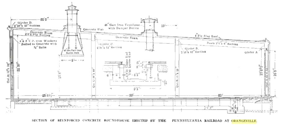
Between columns D is girder D, which is 2 ft. 10 in. in depth and 12 in. in width and and is
reinforced with four 1 in. square twisted rods, two bent up at the ends and otehr reinforcing
to form the eaves and gutter. Between girders C and D the sane beams as between B and C
are continued.
It will be noticed that the span between girders C and D is shorter than between C and B,
which in turn is shorter than between A and B, which accounts for the use of similar concrete
beams, although the roof area supported continually increases.
The roof structure is concrete slabs 4½ thick reinforced by 3⁄8 plain round rods
spaced 6 in. centers across the heams and by 3⁄8shrinkage rods at about 18 in. centers
parallel with the beams. Other reinforcing is installed at the connections with the
various girders and beams. These slabs are covered with four-ply slag roofing.
The openings for the smokle jacks and ventilators are formed in the slabs and eyebolts for
carrying the jacks are embedded in the concrete.
The outer wall of the house is formed by a 9-inch brick filling betwen columns D and below
girder D. This filling is not tied to the concrete work and extends to foundation at
ground level. A large part of the space, however, is taken up by window area, steel
frames and sash being employed, which extend from the concrete girder to about 3 ft. 6 in.
from the ground level where bluestone sills, resting on the brickwork, are located.
These window occupy a space 16 ft. 9½ in. in width, the distance between centers of
columns being 23 ft. 11 &fasl16 in.
The floor consists of 3 x 12 in. plank laid radially, parallel with the pits, on 4 x 6 in.
pine sleepers imbedded in 18 in. of cinders. the floor at the center between pits
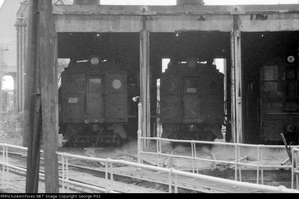
is 4 in. higher than the rail. The doors are of the usual swinging type and are arranged
to swing inward. They are carried from hinges imbedded in in the concrete columns
and give an opening of about 12 ft. Every third pit is provided with a wicket door. &nbdp;
The end walls are of brick filling betwen cooncrete columns and provided with narrow windows
in each panel.
Pits - The pits are of most substantial concrete construction, reinforcing rods being
used wherever the character of the ground made it neccesary. The side walls throughout
are 2 ft. in width and the foundation is at least 12 in. thick at the narrowest point and
9 ft. 1 in. in width, except at the jacking walls, where the width of the side walls is
carried out to 3 ft. 6 in. and the width of the foundation to 12 ft. 1 in. These
extensions for jack foundations are 8 ft. in length and located at the outer end of each
pit on either side and at a point 27 ft. from the outer end of theh pit. The bottom of
the pit it well crowned and h as a slope of 3 in. in its length of o65 ft. inside, draining
toward the inner circle. Here there is a cast-iron grating over a sump, which
connects with a 4 in. cast iron pipe leading to the turntable pit. The rails are
carried on 8 x 12 in. stringers bolted to the top of the concrete wall, as is showm in
the cross section. A 3 x 8 in. oak strip with its upper edge beveled is spiked inside
of the stringer , acting as a protection for the heating pipes, which are secured along
the inside walls of the pit. The roundhouse floor is carried directly uo to the rail
on eitehr side.
Eight pits in the end of the house adjacent to the machine shop are provided with drop
pits. The first two tracks having a drop pit for truck wheels, the next three a drop
pit for drivers, and the following two a drop pit for trailing wheels. The next
pit is provided with a drop table for dropping all the wheels on the locomotive at
once. These drop pits are built with the same general style of walls and floor as are
used in the regular engine pits.
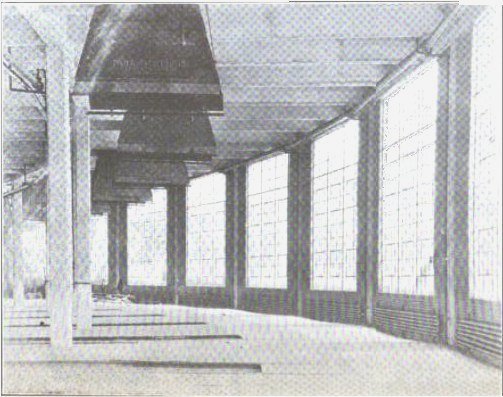
Cast iron smoke jacks, of a new design recently developed by Paul Dickinson, Inc., are
used. These jacks have a length of 8 ft.and are supported from the I- bolts imbedded in the concrete roof slabs. The hood joins a 40-in. diameter circular section made in
two parts, which passes through an opening 4 ft. 6 in. square in the roof slab, provided
with a heavy 8 in. concrte curb for distributing the stresses to the adjacent beams.
The space between the jack and the the foor is covered, but not closed, with a cast-iron
extension forming part of the jack. space being left for ventelation at this point. The
top of the jack has a double hood for protection from rain or snow. In addition to the
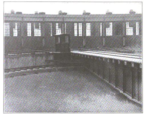
space around the smoke jacks for ventelation there is also provided at anout the center over
each pit. These ventelators have dampers controlled by a sliding weight on the end of
a chain operating gear. Their construction and arrangement are shown in one of the
illustrations.
Lighting - Inasmuch as this type of house is not provided with any overhead natural
lighting, as has been customary in most new houses, special attention was given to providing
large natural lighting area at both ends of the pit, and in this respect, as is clearly shown
in the illustrations, unusual success has been obtained. The windows in the outer circle
are about 16 ft. 9½ in. in width and 18 ft. 10in. high over the frames, a steel sash
known as Detroit Fenestra, maufactured by the Detroit Steel Products Co., is used. For
For large areas of this kind this type of sash has many advantages, not only in its strength
but also in geatly increasing the available lighting area. In each of the large windows
there are six section s arranged to swing on the horizontal axis and provided with controlling
rods for holding in any desired position. On the inner circle the swinging doors have
large sash in each. This gives altogether about 375 sq. ft. of natural lighting area
per pit, not including the windows in the end wall.
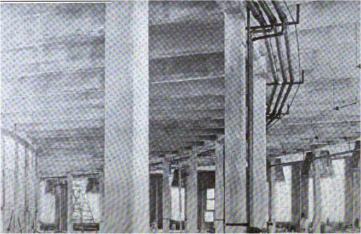
The heating system is by direct radiation and includes four large pipes running the full
length on either side of each pit and a coil consisting of six sections extending the
full length between concrete columns under the windows in the outer circle. This
heating system was designed and installed by the National Boiler Washing Co., who also
furnished the boiler washing equipment. The three pipes used in the boiler washing
and filling system are supported by brackets secured to the concrete beams along the
inside of column B, the connections coming down at every alternate post, as is shown in
one of the illustrations. Similar brackets carry the high pressure steam and air lines
along the top of column C, while the same supply for the heating system is caried in a
large pipeat the top of columns D. The exhaust lines for the heating system are
carried in a conduit just inside the foundation of the outer circle, this being covered with
removable sections of flooring.
The washing tanks and pumps and other apparatus are located
in the powerhouse and pipes are carried to the roundhouse in an elevated wooden trough supported
by steel bents. This same elevated conduit also carries the steam heating lines and other
pipes from the powerhouse.
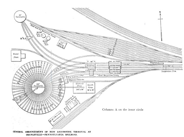
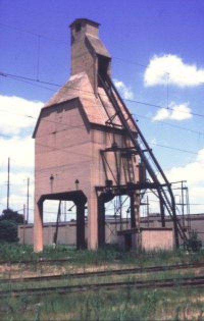
Turntable - The turntable pit has concrete side walls and a concrete ledge for
supporting the circular rail and is floored with brick paving. The table is a
100-ft. standard Pennsylvania type and is propelled by the standard electric turntable
tractor of George B. Nichols & Bro., which operates the turmtable with the heaviest locomotive
at the rate of 60 degs. in 60 seconds.
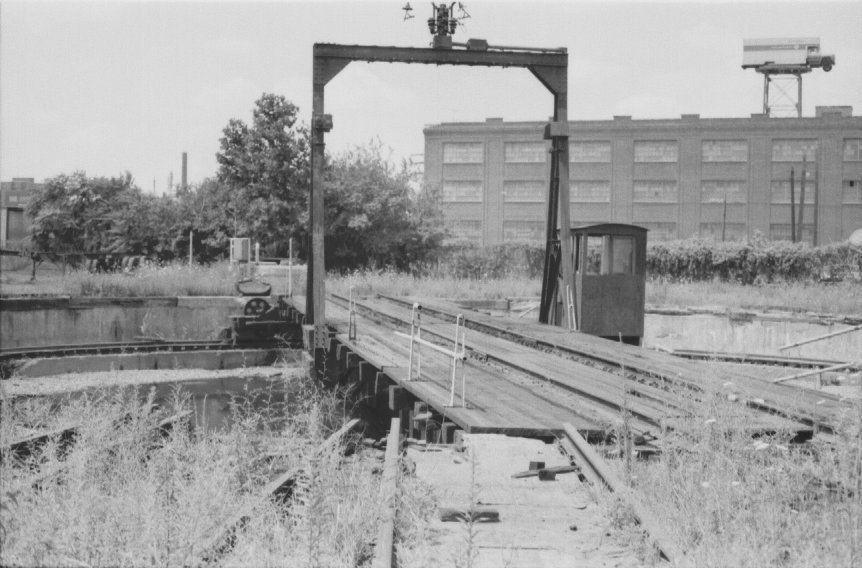
Orangville's (abandoned) turntabke in 1983
This tractor is simply an attachment to the
table and is entirely self-contained. The cab is on the tractor frame and ans all
controlling appliances are located therein. A similar tractor is used on the 85 ft.
turntable at the end of the storage yard. Since this latter turntable is located on
the property line and has entering tracks from but one side, the concrete circular wall
has been carried up about 3 ft. above the surface on the far sideto act as a bumping post
and prevent the locomotives running off the end of the table.
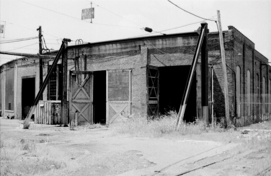
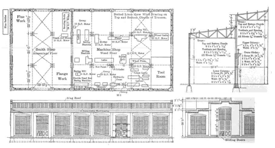
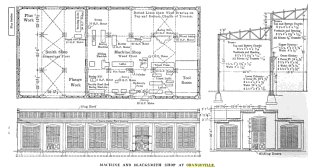
Shop building
A steel and brick structure 80 ft. 3 in. x 162 ft. 10 in. in outside demensions, houses the
machine and blacksmith shop, the two shops being separated by abricl wall. This
structure consists of three bays, the ceter one being carried up to give a row of winsows
on either side. There is a 10-ton crane over the center bay of the machine shop.
The structural details and architectural apperance are clearly shown in the illustration,
as are also the arrangement and list of machine tool equipment. The side windows have
wooden sash and are balanced one with the other, while the windows in the clere-story are
provided with an operating gear, so they can be controlled from the floor level. The
total lighting area of the building in square feet is almost exactly equal to the floor area.
Machine Shop Details
An inspection of the tools provided will show that this shop is prepared to make any class of
repairs on its locomotives if neccesary. The heavier tools are all grouped under the
crane and are largely driven by individual motors, while the smaller tools are in most cases
group driven. One of the tracks in the roundhouse served by the driver drop pit
continues through the outside wall and for the full length of the machine shop. This
permits the loading and unloading of heavy parts by means of the crane and also allows a
locomotive to be drawn into the shop and the crane used for dismantling.
Inside machine shop in 1983
The shop is heated throughout by direct radiation, with the coils under the windows on
the side walls. The roof is of four-ply slagroofing laid on ¾ sheathing.
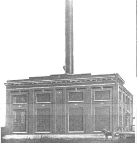
Powerhouse
A structure which far exceeds in its architectural
beauty anything usually associated with a locomotive terminal, encloses the powerhosuse at
Orangeville. It consists of a practically square building of brick with granite
footings and terra cotta trimmings, with a steel stack without stays located in almost the
exact center. An extensio on the rear of 31 ft. 9½ by 34 ft. 7 in. outside
is provided for the boiler washout system. The windows,
which occupy a large portion of each panel, have steel sash. The structure has a
steel framework, the center row of posts dividing it into two bays, one 35 ft. in width
and the other 42 ft. in width, the latter being the boiler room and the former the engine
room. Brick filling between these columns forms a wall between the two sections.
Over the engine room there is a 10-ton crane furnished by Alfred Box &
Co. Entrances are provided to the boiler washout section from both the engine and fire
room and there is but one opening between the boiler room and the engine room and this is
provided with an Underwriter's automatic fire door.

Powerhouse, 1911
In the fire room there are installed three Sterling boilers, with a space left for anotehr
unit. The coal is brought in the track alongside the northrn wall and discharged
on the floor in front of the boilers. The ashes fall into the basement where there is
an ash handling apparatus which discharges them into cars standing on the coal receiving
track. The boler feed pumps and feed water heater are located in the boiler room
between the batteries of boilers and beside the stack foundation. There are nine
24-inch ventilators over the top of the boilers and five similar ventilators in the engine
room. The foundation for the stack is a solid block of concrete 20 x 20 x 13 ft.
brought up slightly above the floor level and to this the steel stack is bolted direct.
In the engine room there is a 250 k. v. a. amd a 100 k. v. a. Westinghouse generator, which
furnish current at a pressure of 220 volts, 60 cycle. A25-kw steam turbine driven exciter
provided for starting the main alternators, which afterwards receive their exciting current
from a motor generator set. The air compressor is also located in the engine room.
Oil house
A fireproof structure, brick walls on concrete foundations with steel trusses, is used
for the oil house. Its main concrete floor is is on a level with the platform along
the track and the oil tanks are in a shallow basement below. The delivery faucets, of
course, are in the main delivery room and air pressure is used to elevate the oil.
The basement contains steam heating coils over the tanks and the arrangement for filling
both from tank cars and barrels has been carefully worked out.
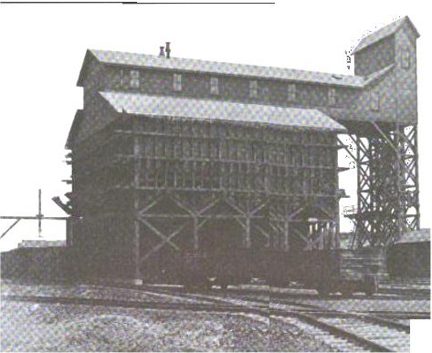
Coaling station
The coaling station, which is of timber construction throughoutm is of the Holman - Barrett
type as designed by Roberts & Schaefer Co., who erected it. The elevating equipment
consists of a pair of 2-½ ton Holman buckets and the distributing means consist of
a pair of Barrett automatic distributing cars which work in time with the Holman
buckets. The total storage capacity of the plant is 1,200 tons of coal and 100
tons of sand. Coal is received on two tracks with a receiving hopper under each.
Both hoppers feed to the one pair of Holman buckets. Interposed between each hopper
and the buckets is a pair of Barrett revolving measuring feeders so arranged that the buckets
are taking coal from one hopper only at a time.
The elevating buckets and distributing cars not only handle coal, but also handle the wet
sand, delivering it into a large overhead bin. This bin has a concrete floor and underneath
are two stove dryers in a fireproof compartment. The sand gravitates through the dryers
over screens into hoppers underneath, from which it is elevated to three storage tanks
overhead. These in turn deliver the sand to three tracks. There is also
a compartment for coke and for hard coal. The plant is electrically operated
and serves three tracks with coal and sand.
The water supply is obtained from the city and is pumped into two steel tubs, each of
50,000 gallons capacity, which furnish the pressure for the standpipes and general service.
The boiler feed pumps, washout equipment, etc., draw their supply from these same
tanks.
There are fire hydrants located freely throughout the whole terminal, there
being at least one in the vicinity of every building.
Storehouse and office building
This is a two-story structure with brick walls and woden floors supported by iron
columns. it contains the master mechanic's office, drafting room and
storehouse. In the latter there is an elevator serving the basement and both floors,
and a loading platform extends the full length of the building. Fireproof vaults of
sufficient capacity to hold all valuable records rae provided.
Adjoining the storehouse is a small brick structure which includes a large reading room and
rest room, communicating with the engineers' locker room, where expanded metal lockers
of large capacity and in sufficient numbers have been installed for the convenience of
train and shop men. &nnsp;adjoining the locker room is a large wash and toilet room.
The whole structure has concrete floors, excellent natural lighting and generally attractive
surroundings.
For more general information regarding locomotive servicing facilities, you
can check out my page General railroad practices,
which is derived from the book Maintenance of Way and Structures
by William Clyde Willard
First Edition, Second Impressio © 1915 by the McGraw-Hill
Book Company, Inc., or you can read the entire public-domain book at Google Books.
Oh - as a final, sad note to close out the history of Orangeville, here is all that was left
in 2010:
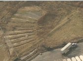
The end of Orangeville
The arc-shaped imprint was the roundhouse; the grassy areas between the concrete are where the
inspection pits used to be. To the right of that impression is a large, grassy arced
area; this was the turntable pit. The grass grew in these areas because they filled in
the holes that were left behind when they tore down the structures. No one planted
anything; no wild flowers popped up - only weeds. Hardly a rememberance befitting the
Standard Railroad Of The World
This was Orangeville -
Where giants once roamed...
 |
Don't race trains...
even if you tie, you lose |
 |

 |
1st set of Orangeville pics |
|
2nd set of Orangeville pics |
|
Photos of Orangeville when it was active |
 |
Camden Yards page |
 |
Mike's Railroad Page |
Last updated Friday, March 1, 2002
Last updated Friday, February 8, 2012
Page text and original photographs &cop; 2012 Michael Calo. NO USE permitted without consent